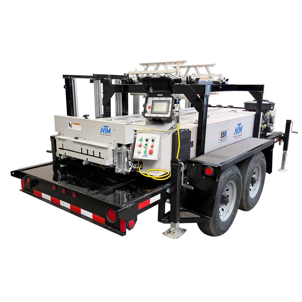
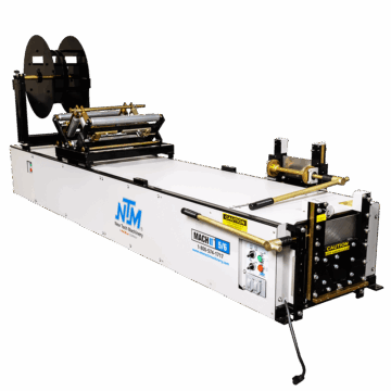
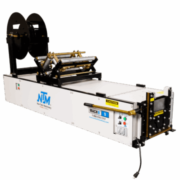
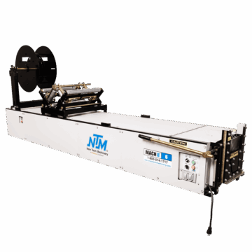
Flagship
Roof & Wall Panel Machines
Do you own or have you recently purchased a WAV™ machine? Changing a profile is an important part of owning your machine. That’s why Nate Roston, Outside Service Manager, walks you through the process step-by-step.
WAV™ manual: https://newtechmachinery.com/learning-center/manual/wav-wall-panel-machine-manual/
Learn more about the WAV™ here: https://newtechmachinery.com/learning-center/the-enhanced-new-tech-machinery-wav-wall-panel-machine/
8 Common Adjustments You Should Know For NTM’s WAV™ Wall Panel Machine: https://newtechmachinery.com/learning-center/video/8-common-adjustments-you-should-know-for-ntms-wav-wall-panel-machine-video/
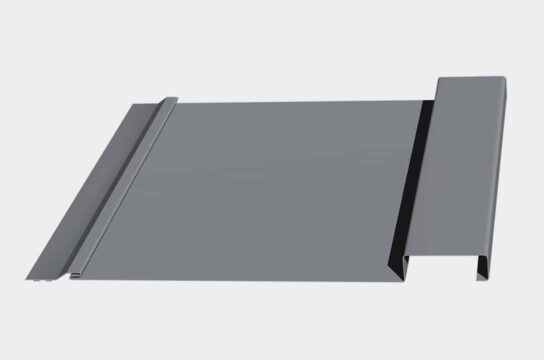
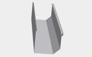
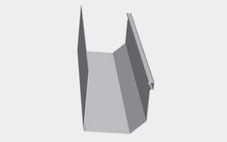
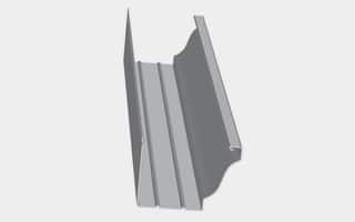
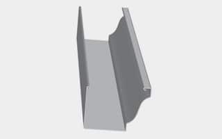
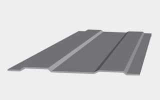
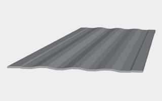
So if you own a New Tech WAV panel machine, follow the steps in this video to learn how to switch it from the 16-4F panel to the 12-1F panel.
Hi, Nate Roston here with New Tech Machinery and in today’s video we’re gonna go over how to change the NTM WAV panel machine from the standard 16-4F panel to the 12-1F panel.
Now as you can see, that we have all the safety covers in place and it’s always good that no matter what, when you’re using the machine, the covers are always in place, especially the shear cover. As you can see, we have the warning label here. So just to remind you never to reach through the shear, always work on front of the shear or in back of the shear.
As you can see that we’ve disabled the machine by using the lockout tagout system so that the machine can inadvertently turned on and powered up. Make sure that you obey the laws of your local jurisdiction. Now the machine has been safely powered off and locked out and tagged out, we’ll now begin to remove the safety covers.
So in order to do the changeover, you’re gonna need a 7 32nd Allen wrench, a half inch socket for the shear, a three eighths wrench for the shear guard and a tape measure. Now we’re gonna be following the steps you’ll find in the manual. See the link below and that’ll lead you right there.
So the first step is gonna be to disengage stations one through 14 so that you’re basically gonna be running a flat panel. So we start by loosening up the flathead screws on either side and then we’ll raise that up and we can tighten up those flat head screws. Now we’re just gonna go all the way down and raise all the rest of them to disengage them.
So once we have stations one through 14 disengaged, the next step would be to go to the entry guide. Like any new tech machine, we’re always talking from the entry end to the exit end. So the right entry guide is gonna be moved from the original 16-4 position to the 12-1F position, which is gonna move the right entry shoe to the left four and five sixteens of an inch. Now we’re gonna go over four and five sixteens of an inch. Use our tape measure from the original position.
Now for the next step, we’ll have to measure the distance between the two rails on the exit end. They’re typically about 22 and three sixteenths, which is right where we’re at. So we’ll have to remove the safety pin for the crank handle and then you’ll notice that the crank handle doesn’t engage until you push in. Once you push in, we’re gonna move this counterclockwise to bring it together four inches. So we’re going from 22 and three sixteens basically to 18 and three sixteens.
So now that we have set our width adjustment for the 12-1F, next step would be to install the auxiliary long guide rod. To install the guide rod I need to install these brackets first and they’re gonna mount right directly to the side of the forming, the number one and number two forming roller stations. We’ll leave those hand tight until we get that rod in place. Once we tighten it up, then we’ll be able to position that in the right spot. So the first bracket goes in between stations one and two. The second bracket goes in between stations five and six. And all these brackets are the same, so we’re going in the same spot.
So now we’re gonna feed the the long auxiliary guide rail over the top of the entry guide and in between the bottom guide rail or guide rod and the the forming rollers, and tighten up the brackets.
Next step is to install the short auxiliary guide rod and it goes right below the flat panel option guide roller assembly. And this mounts directly to the side of drive number five and drive number six. We’re just fixing these blocks to the side of the drive and then we’ll tighten up the guide rod itself. Tighten up the bolt on the short auxiliary guide rod.
So the next step would be for us to set the left entry guide and run a piece through the machine. So I cut a small piece of coil, about a seven foot long piece and I got it in my entry guide. Now I’ll bring the other shoe over just to where it’s barely touching the edge of the material. Make sure it’s nice and smooth, that it doesn’t shift back and forth.
Now I’m ready to run my test panel. So once we got our sample piece cut, the seven footer and the entry guide set, now we have to enable the machine so that we can run our test panel. So this is where we need to be extra careful and make sure that we keep all of our body parts out of the moving parts of the machine, especially the shear. So now is where we would remove the lockout tagout mechanism.
All right, so we’re just gonna feed our piece through slowly. Always make sure when you feed the material through that you go slowly through each station to make sure that you don’t have any collisions. So now that we have our sample piece brought up to the shear, we’ll begin to set up the shear for the 12-1F WAV panel. Before we do that, we want to reinstall our lockout tagout just to be safe.
So now that we’ve ran a part up to the shear and then we’ll begin to set up our shear dies for the 12-1F, we’re gonna remove the shear guard and cover and then we’ll be working with the shear. So again, we wanna make sure that you’re working safely. So it’s always important to work on the front of the shear or the back of the shear, but never reach through the shear. We’re removing all of the shear dies ’cause we will not need these for this next profile. We have a different profile that we’re gonna be using for the 12-1F. We’ll set all these aside.
Now we’re working on removing the shear dies on the entry side of this shear, and you’ll notice that we’re not reaching through the shear. We’re able to do this just by reaching on the backside of the shear. Our hands are safely out of the way. After we’ve removed the shear dies, next we’ll have to reconfigure the upper blade to accommodate the 12-1F profile.
So we’re gonna start by removing the number four blade. And then the blade that we use to cut the hem, we’re gonna move that over one hole. So once we move this over, we’re gonna have three holes exposed, but there’s a drawing of the configuration for the 12-1F profile in the manual. Now we’ll move all the other blades over one hole.
So now that we have our sample piece brought up to the shear and our machine disabled, we’re gonna begin to install our shear dies starting with the hemming die. Okay, so the inside die for the the hem actually has this piece that goes in to support so it doesn’t close the hem, but you also have this cam follower that has to go inside, which fits through this hole into shear.
So we kind of have to go in there right above it and then stick the cam follower in there. And keep in mind, whenever you’re working with the shear, not to ever stick your hands through the shear, always working front of the shear or behind the shear, but never through the shear. The outside piece also fits the other end of the cam follower.
So we like to start with the hem die because it gives you a line precisely where we wanna align it according to the panel. So we’re gonna bring this line right to the edge of the hem on the female side, and then that’ll pretty much line everything else up all at once after we do that. So once we get this into position, you’ll notice that there’s a bar in the back of this shear that goes between the two blades. Well, we just have to move the upper bar to where that bar rides right up against that upper blade and then that pretty much establishes where we need to be.
Now the other part is we basically have to install our 12-1F shear dies and then that’ll complete the process. Then right alongside of that goes our 12-1F shear die. These dies here take three bolts. We’ve already got our panel up in position.
So we’ve got the piece through the shear, everything looks good. We’re gonna tighten up everything, make sure that all is secure. Then we’ll do a test cut, run the rest for our panel out. So now that we’ve got our piece, our shear line piece ran through, we’ll just do a test cut and then we’ll run a sample piece out.
So now that we run our test piece, this is your 12-1F panel, and if you need to make adjustments, see the video link below for the adjustment video.
So now you can reinstall your safety covers and go to your job site and run your panels.
Thank you for watching. We’ll see you in the next video.


Machine tutorials, maintenance tips, industry insights.