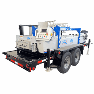
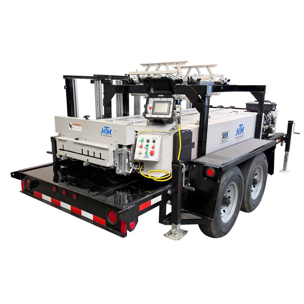
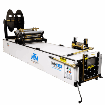
How to Install the EZ-Counter on Your Gutter Machine
Follow this step-by-step guide and video to learn how to install your EZ-Counter controller to an NTM gutter machine.
/Rick Zand/4 min read
The EZ-Counter is a valuable addition to your gutter machine, providing precise control and measurement for your projects. Follow this step-by-step guide to install and set up the EZ-Counter for optimal performance.
Tools You’ll Need: • Drill • Driver with a 5/16″ bit • Hammer • Phillips and straight screwdrivers • Pliers • Dykes (wire cutters) • 7/16″ ratchet and wrench • Measuring device
Step 1: Prepare the Machine
Unplug the Machine For safety, ensure your gutter machine is unplugged before beginning. You’ll need to remove the covers, so take this precaution seriously.
Organize Your Components Lay out the EZ-Counter manual, installation directions, and all necessary parts for easy access.
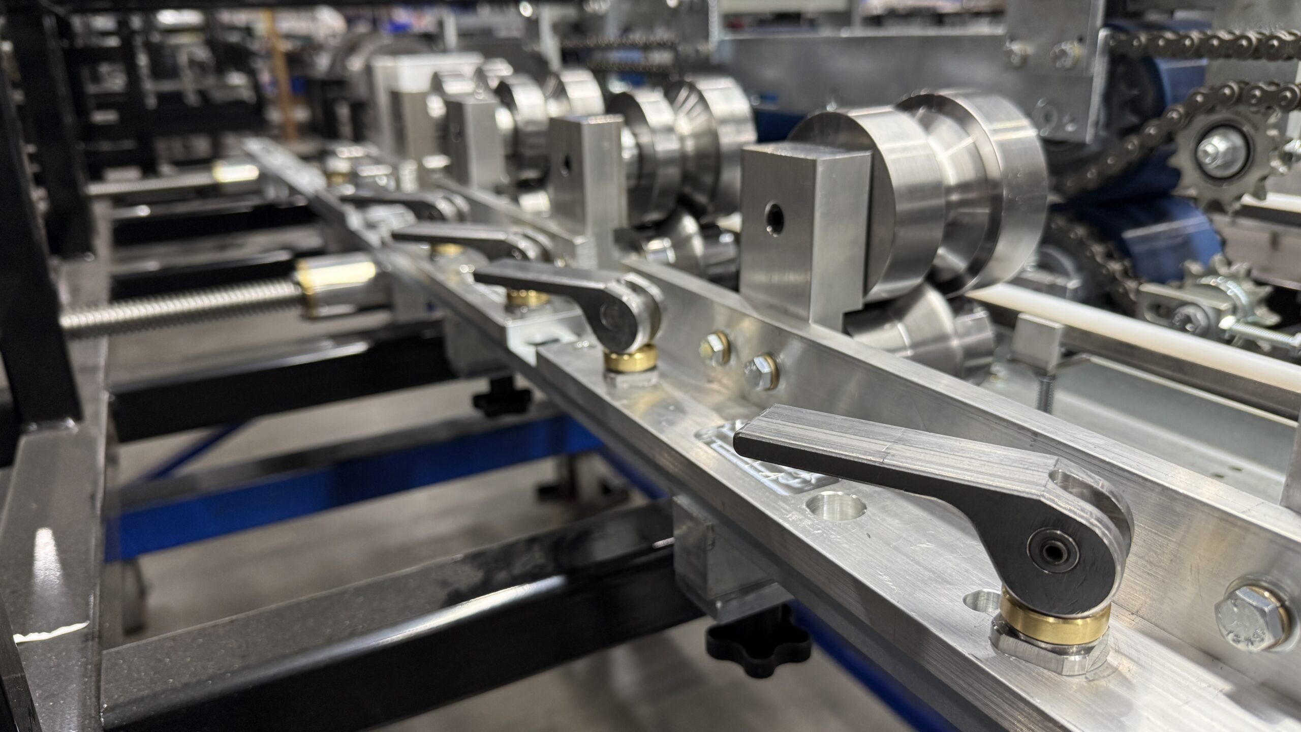
Step 2: Install the Encoder
Prepare the Encoder Block o Remove and discard the nut from the encoder. o Add washers to create space for the wire cable to clear. o Attach the encoder block, ensuring the recessed holes face outward.
Position the Encoder o Mount the encoder below the skate and inside the keel. o Align the encoder wheel slightly above the roller pass line. o Tighten the screws securely, but avoid overtightening. o The encoder will be mounted on the back end of the machine just below the skate inside the keel.
Adjust Spring Tension o The encoder wheel should be placed just above the pass line so that when the material comes through, it pushes down with spring tension. o Use the spring tensioner to ensure proper contact between the material and the encoder wheel. o Bolt the top plate to strap it to the skate bar and hold it in place.
Step 3: Wire the Encoder
Route the Wire o Run the cable through the designated pathways, avoiding pinch points. o Secure the cable using wire ties to keep it from interfering with machine operations.
Connect the Cable o Attach the encoder cable to the extension cable. o Ensure the connection is tight to avoid future adjustments.
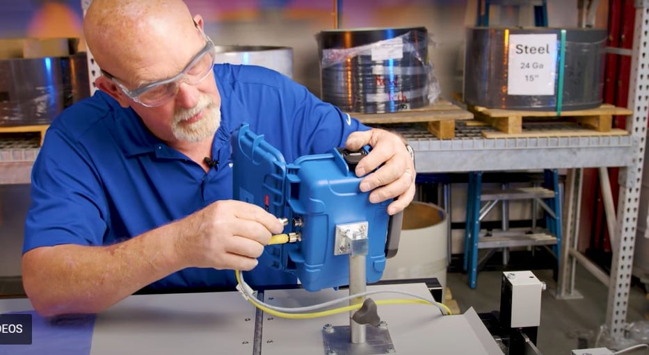
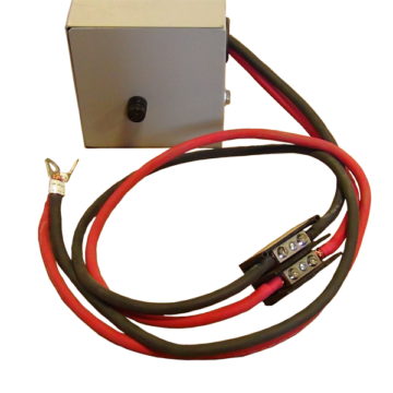
Step 4: Install the Control Box
Prepare the Cable o Trim the cable to length, leaving about 16 inches for the strain relief. o Remove the plastic support and ground cable from the wiring.
Attach the Strain Relief o Feed the cable through the strain relief, leaving a small amount of slack. o Secure the strain relief to the box.
Follow the Wiring Diagram o Reference the included wiring diagram for proper connections. o Connect the wires (blue, brown, white, pink) to their respective terminals (L2, L3, A1, A2). o For mounted controller, cap off unused wires (red and green).
Wire the EZ-Counter with the Wireless Remote Connect the P2 Terminals o Locate P2-5 and connect it to the red wire, ensuring a secure twist. o Locate P2-4 and connect it to the green wire in the same manner. o Locate P2-2 and connect it to the gray wire, double-checking the terminal number for accuracy. Connect the Yellow Wire to the New Relay o Take the yellow wire and attach it to terminal 14 on the new relay. Reposition the Red Wire o Remove the red wire from its original position. o Connect the red wire to P2-3 and secure the connection with a wire nut. Ensure all connections are tight and properly insulated to avoid loose wiring or interference during operation.
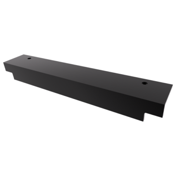
Step 5: Mount the Cover Plate
Measure and Align o Position the plate 6.5 inches from the edge of the cover to the edge of the plate, and 3.75 inches from the edge of the plate to the hinge. o Secure it using bolts, washers, and nuts.
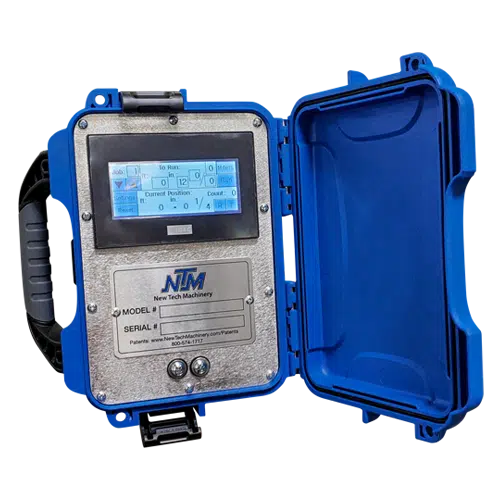
Attach the EZ-Counter o Mount the EZ-Counter using its swivel connector for flexibility. o Connect the gray wire to the encoder and the yellow wire to the control box.
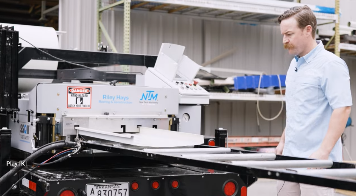
Step 6: Test the System
Power On and Test Functions o Turn on the EZ-Counter and check for a proper display screen. o Test the forward, reverse, and run functions.
Program Measurements o Enter specific lengths, including custom settings like miters. o Verify the counter runs accurately and adjusts as programmed.
Once installed and calibrated, the EZ-Counter provides precise control and versatility for your gutter machine. With features like miter programming and customizable settings, it streamlines your workflow for improved efficiency. Also, take a look at the best accessories for your Mach II Gutter Machine.
For more tips and product information, visit the NTM Learning Center. For information about our gutter machines, or any NTM products, contact us.