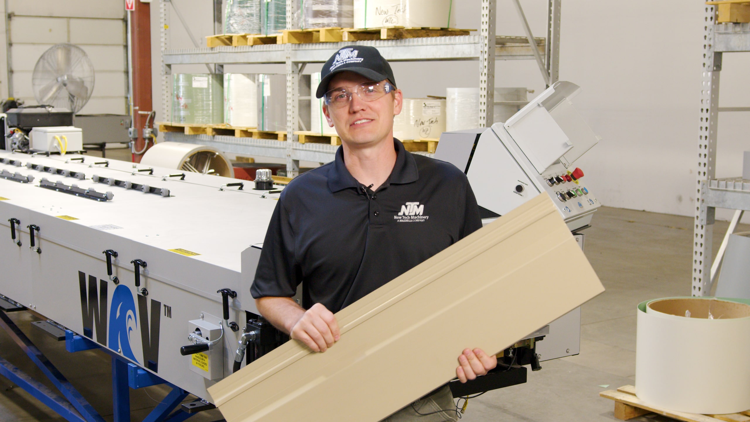
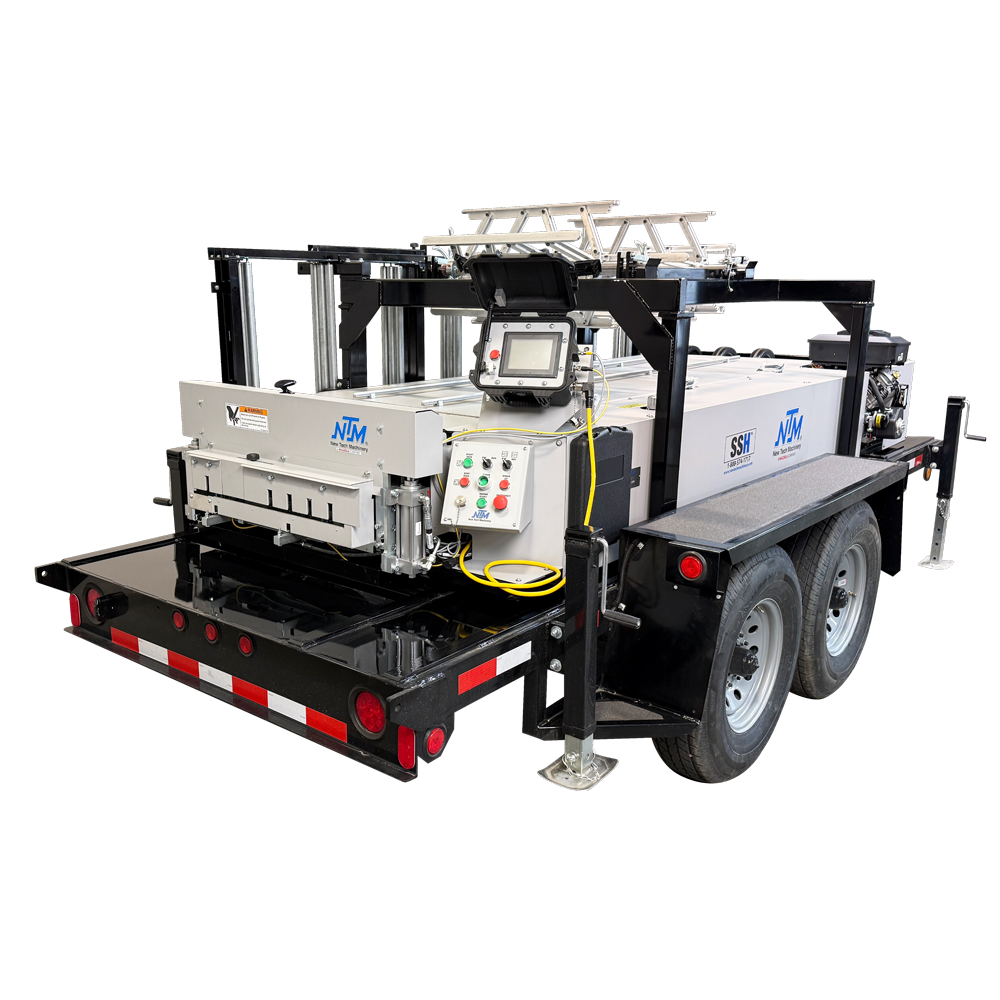
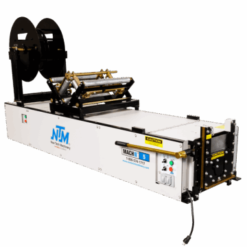
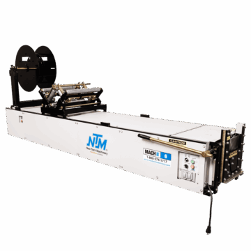
Converting Your WAV™ Machine from the WAV 8-1F to the WAV 12-1F
Owner of a WAV™ Wall Panel Machine? Find out how to do a profile changeover from the 8-1F to 12-1F following the steps in this article and accompanying video.
/Rick Zand/5 min read
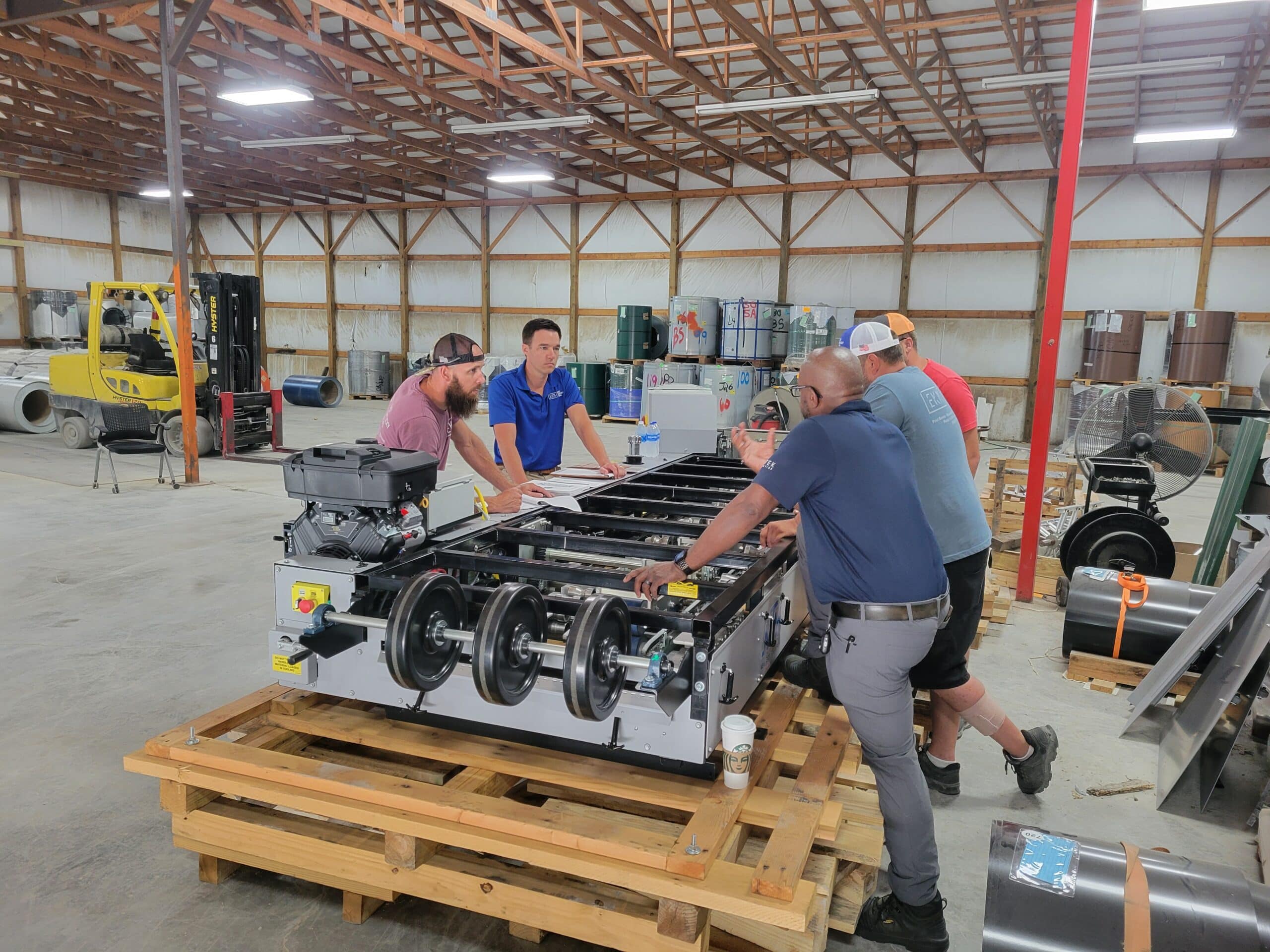
At New Tech Machinery (NTM), we’ve helped metal contractors by providing the highest quality portable rollforming machines and machine support. We feel it’s important to educate our machine owners on how to operate their machines to their full potential. This includes showing you how to make adjustments to the machine and tooling when necessary. In this article, we will show you how to convert the WAV™ Wall Panel Machine 8-1F profile to the 12-1F profile.
Converting your New Tech WAV machine from the WAV 8-1F to the WAV 12-1F model is a detailed process that requires careful attention to safety and precision. Ensure that your machine’s covers and guards are securely in place and that you fully understand all warning labels before proceeding.
Make sure the shear guards are properly in place. When working with the shear, always have your hands in front of or behind the shear, but never through the shear.
Implement lockout tagout procedures to ensure the machine is powered down and secure.
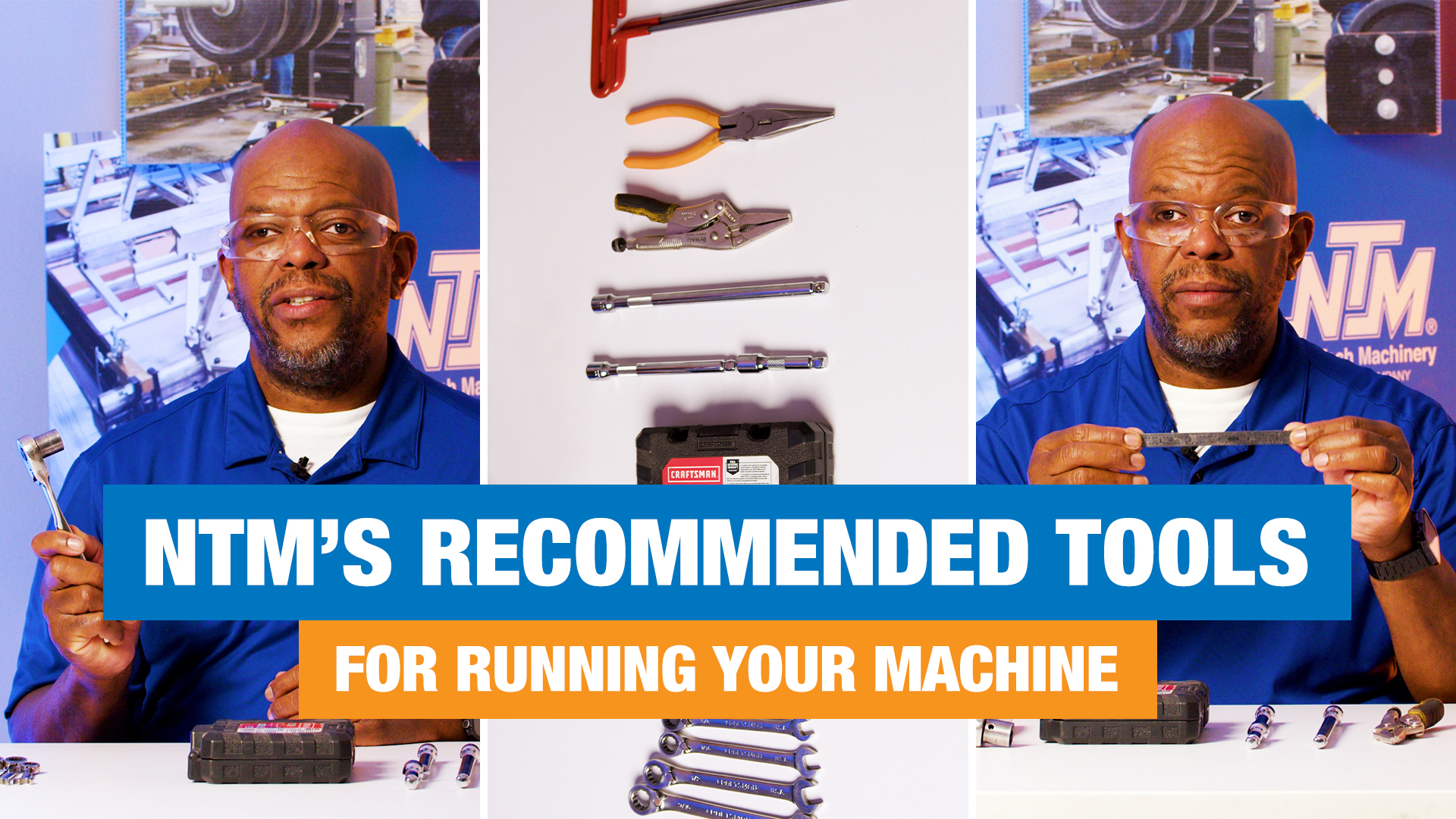
Remove all machine covers using a ½” wrench and a 3/8” wrench.
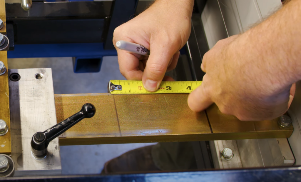
Adjusting the Entry Guide:
Right-Side Entry Guide
Start by measuring 4-5/16” from the factory witness mark. Before moving entry guide, witness mark the current position for future reference.
Loosen the adjuster handle and move the adjuster to the 4-5/16” mark.
Tighten the handle, lift, and point it back into the machine.
Left-Side Entry Guide
Use a 17-9/16” inch sample piece to adjust the left side entry guide.
Open the left-side entry guide and insert the material.
Bring the left-side entry guide in until it’s snug against the material.
Slide the material to ensure that it can move smoothly through the machine without shifting left and right.
Measure 4-5/16″ from the factory witness mark.
Adjusting the Center Forming Rollers and Auxiliary Guide Rods:
Steps 6-7 in the owner’s manual
Confirm that all center forming rollers are in the up position and secured.
Also, ensure the upper and lower auxiliary guide rods are in place.
Adjusting the Exit Guide
Use the adjusting handle to set the width of the tooling for the new material (clockwise=out; counterclockwise=in).
Adjusting the Tooling Width:
Go to the right-side exit of the machine.
Write the current width directly onto the gold bar for future setups.
Add 4” to the width from the inside of the gold bar on the left side to the inside of the gold bar on the right side by turning the handle out (counterclockwise).
Lock the handle.
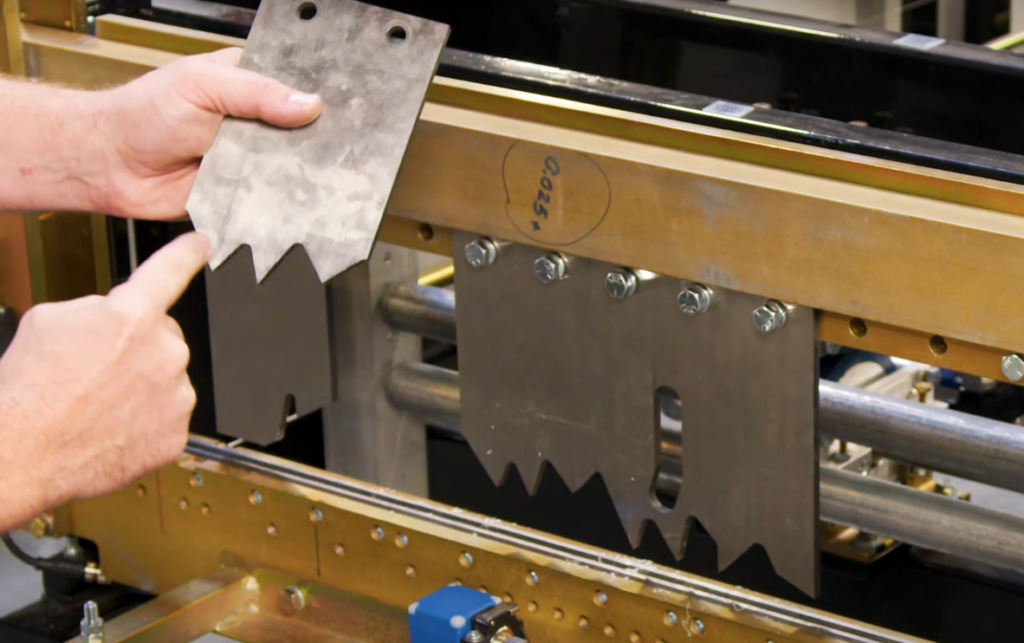
The longer tooth of the blade should face outward.
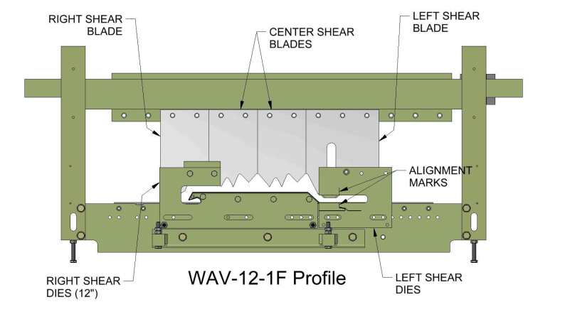
Modifying the Shear Area: Replace the 8-1F Shear Blades With 12-1F
Steps 10-18 in the owner’s manual
Ensure you’re working safely around the shear, never reaching through it.
To add the shear blade, change the entry, and exit profile dies, you’ll need a 9/16” and a ½” wrench.
Mark original alignment locations “8-1F” on the shear blade with witness marks for future changeover reference.
Loosen the die bolts and remove the dies and bearings.
Loosen all the shear blade bolts to move the blades out.
Move the number 1 blade out so there are two exposed bolt spots outside of it.
Install the number 2 blade into the empty space. The shorter end of the blade should face inward.
Tighten all the bolts to secure the blades.
Refer to the manual for proper shear blade placement and secure all new components in place, with the center shear.
Setting up the Shear Mechanism:
Loosen the bolts on the shear mechanism and adjust its position according to the new profile needs.
Bring material through the machine to align and install the new shear profile dies correctly.
Use the machine in maintenance mode to jog material through for alignment checking, ensuring to stay clear of moving parts.
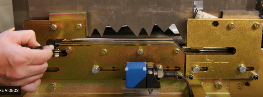
Final Die Adjustments and Testing:
Installing Exit Dies
Put the machine in maintenance mode and remove the lock from the power switch.
With the E-stops pulled out on the controller, start the hydraulic pump.
At the entry end of the machine, confirm the alignment of shear dies and blade by incrementally jogging material to a few inches behind the shear blade. Listen for any potential issues as it passes through the tooling.
Put the lock-out tag-out in place.
At the exit end, line up the left exit die with the blade tooth.
The right-side die should nearly touch the left side die.
Power the machine, bring the material through the shear, and perform a test cut using the maintenance mode controls for safety.
Installing Entry Dies
Reverse jog the material about 8” to install the entry-side shear dies.
Turn power off and lock-out tag-out.
Install left-side entry shear die.
Install right-side entry shear die.
Note: The entry die is slightly larger than the exit die. Make sure you have consistent offset on both the left and right with your entry and exit die alignment.
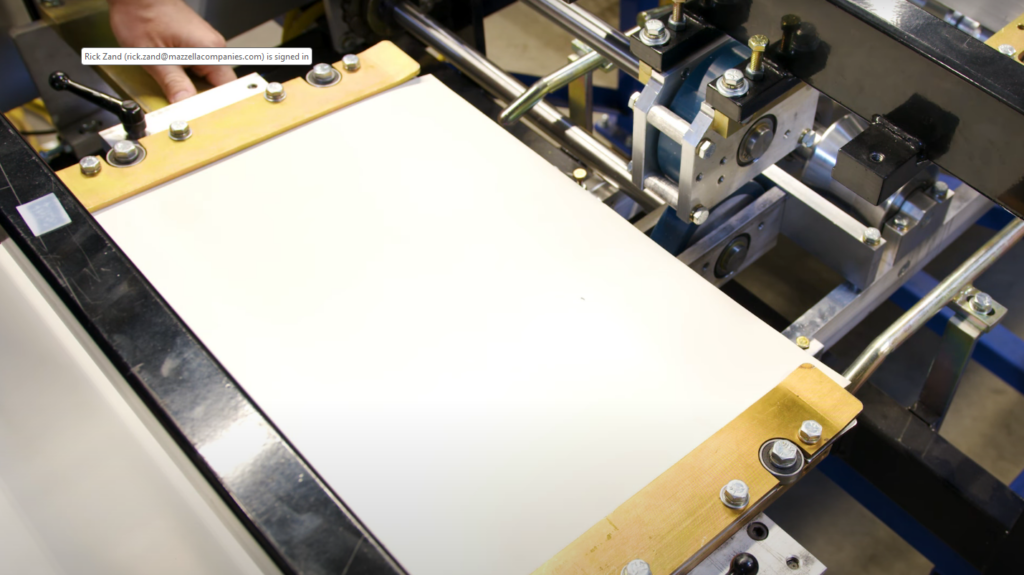
Run Test Panel
Power the machine and perform a test cut in maintenance mode.
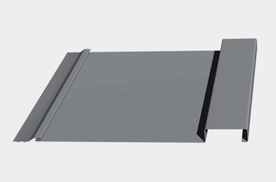
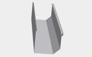
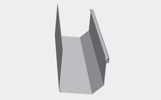
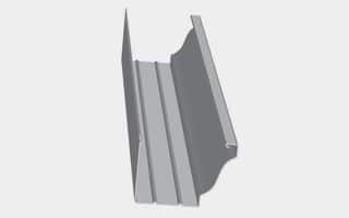
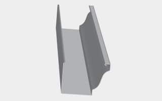
Inspect the first sample panel produced for correct dimensions on the hems and legs, and make sure no further adjustments are necessary.
Final Steps
1. Reinstall Covers and Guards: Reattach all covers and guards on the machine before using it.
2. Contact for Support: For additional information or support, contact us.
Following these steps will ensure a safe and accurate conversion of your New Tech Machinery WAV Machine from the WAV 8-1F profile to the WAV 12-1F profile. Always prioritize safety and refer to the official guides for additional assistance.